What is an ECG?
The electrocardiogram, or ECG, is a simple diagnostic test which records the electrical activity of the heart over a set time period via the process of attaching a series of electrodes at particular points on a patient’s body.
Many medical students, and even some more experienced medical professionals, struggle with ECG interpretation. If a stepwise, logical approach is taken the ECG should be a simple process and can provide an immense amount of useful information, especially when used in conjunction with a patient’s clinical presentation. The ECG is undoubtedly one of the most useful investigations available to us in medicine.
The Electrical Conduction System of the Heart
In order to be able to interpret an ECG, a basic understanding of the heart’s electrical conduction system is required. The heart is often compared to a pump that is made up of muscle. The pumping action of the heart is controlled by the cardiac conduction system.
The sinoatrial node (SA node) is the pacemaker of the heart and is the point of origin of the electrical impulses that are propagated through the heart. The SA node is located in the right atrium and automatically generates an electrical impulse 60-100 times per minute under normal conditions. These electrical impulses stimulate the atria to contract and then travel to the atrioventricular node (AV node), which is located in the inter-atrial septum. Here the impulse is briefly slowed before continuing down the conduction pathway to the bundle of His. The bundle of His divides in the septum between the two ventricles into the left and right bundle branches, which are situated in the left and right ventricular muscle respectively. Conduction then spreads out via specialized tissue within the ventricular walls known as Purkinje fibres.
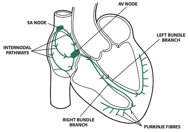
Figure 1. The cardiac conduction system © Medical Exam Prep
Placement of Electrodes
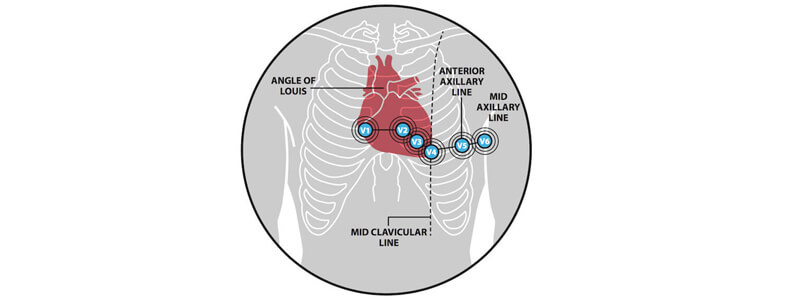
The correct placement of electrodes is vitally important as misplacement can result in misinterpretation and missed or incorrect diagnosis. Somewhat confusingly a 12-lead ECG only has 10 electrodes. These 10 electrodes allow the electrical activity of the heart to be looked at from 12 different positions. There are 4 limb electrodes and 6 chest electrodes and their placement is as follows:
Chest electrodes:
- V1 – Right sternal edge, 4th intercostal space
- V2 – Left sternal edge, 4th intercostal space
- V3 – Midway between V2 and V4
- V4 – Left midclavicular line, 5th intercostal space
- V5 – Anterior axillary line, 5th intercostal space
- V6 – Left midaxillary line, 5th intercostal space
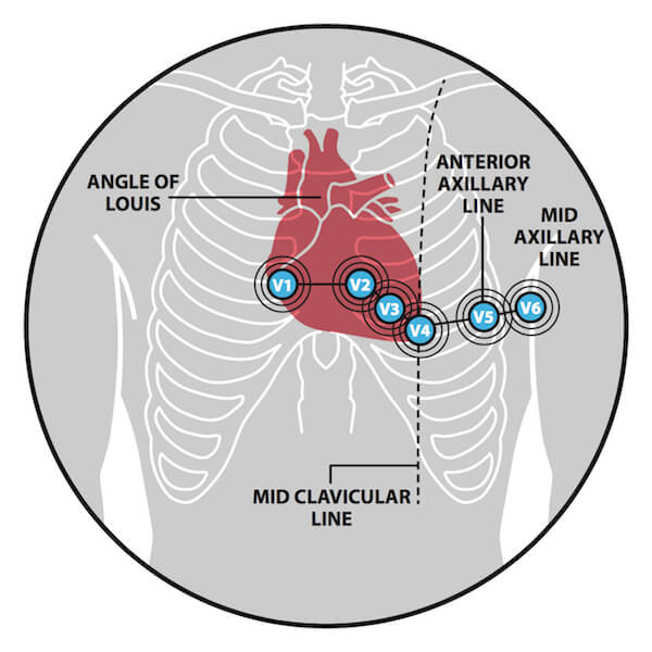
Figure 2. Placement of chest electrodes. © Medical Exam Prep
Limb electrodes:
- LA – Left arm (between shoulder and elbow)
- RA – Right arm (between shoulder and elbow)
- LL – Left leg (above the ankle and below the torso)
- RL – Right leg (above the ankle and below the torso)
The lead attached to the right leg is a neutral lead and is solely present to complete the electrical circuit. It plays no role in the formation of the ECG itself.
Lead Groups
An ECG lead is not actually a physical lead but instead a view of the hearts electrical activity from a particular angle across the body. The 10 electrodes provide 12 views, hence the term ’12-lead ECG’.
The ECG leads are grouped into two electrical planes, horizontal and vertical. The chest leads view the heart from a horizontal plane whilst the limb leads view the heart from a vertical plane
The Chest Leads:
There are six chest leads; V1, V2, V3, V4, V5 and V6. These are unipolar leads as they only have one associated electrode. The positive pole is the electrode itself and the negative pole is the centre of the heart. These leads look at the heart in a horizontal plane from the front and left side. Leads V1 and V2 look at the right ventricle, leads V3 and V4 look at the septum and leads V5 and V6 look at the anterior and lateral walls of the left ventricle.
The Limb Leads:
The limb leads are leads AVR, AVL, AVF, I, II and III. Each of these leads represents a measured voltage that also has a direction. By combining the magnitude of the measured voltage and the direction of the voltage a vector is formed.
The limb leads AVR, AVL, AVF are also unipolar leads as they only have one associated electrode. The voltages of these electrodes are very small and have to be ‘augmented’ by built-in amplifiers. The ‘AV’ used in the terminology for these leads, therefore, stands for ‘Augmented Vector’. For these leads, the negative pole is once again the centre of the heart and the three leads create a triangle with the heart in the middle. The vectors created are shown below in figure 3:
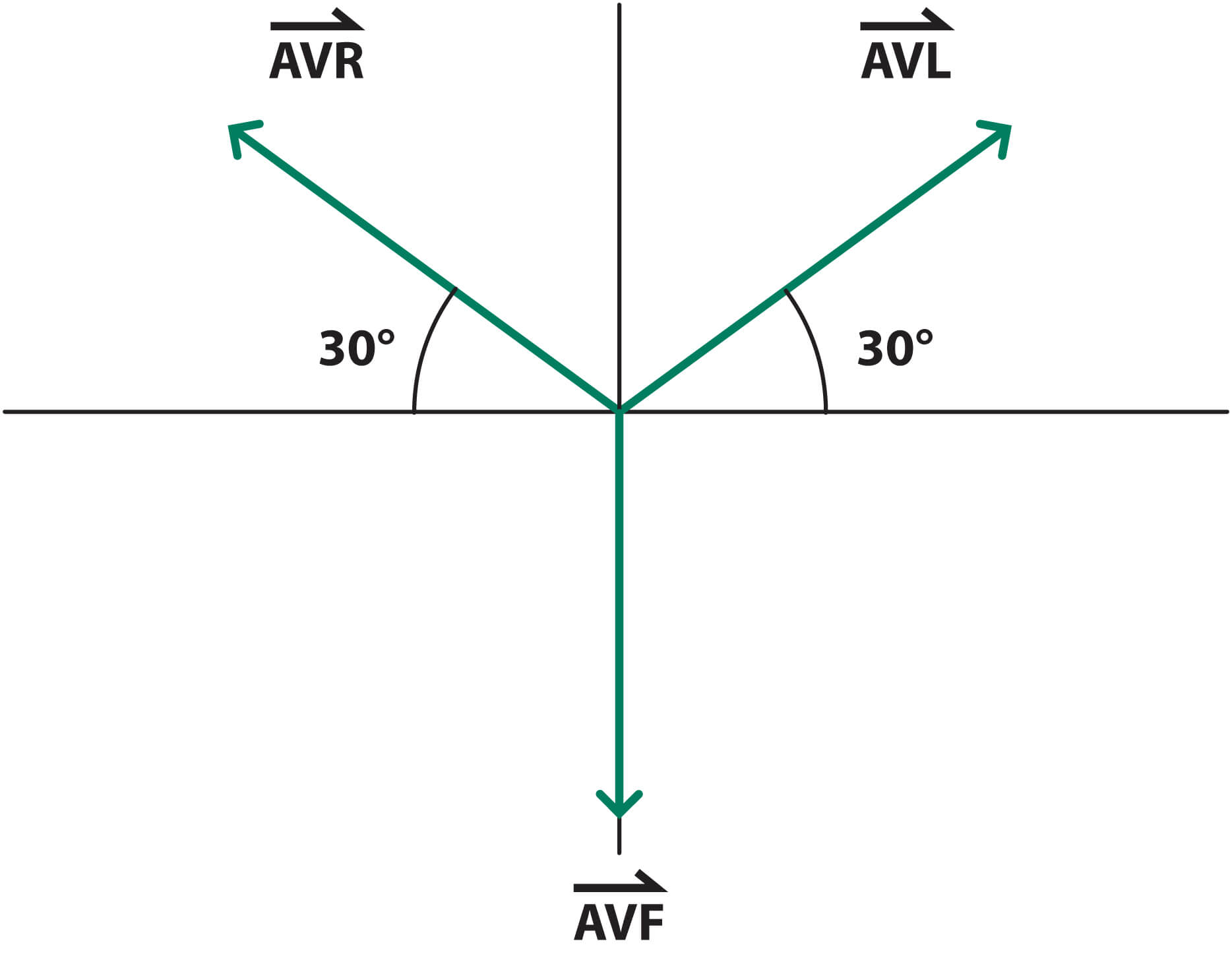
Figure 3. Limb leads AVR, AVL and AVF. © Medical Exam Prep
The limb leads I, II and III are called bipolar leads because they have two associated electrodes. AVR, AVL and AVF make up an equilateral triangle, known as ‘Einthoven’s Triangle’.
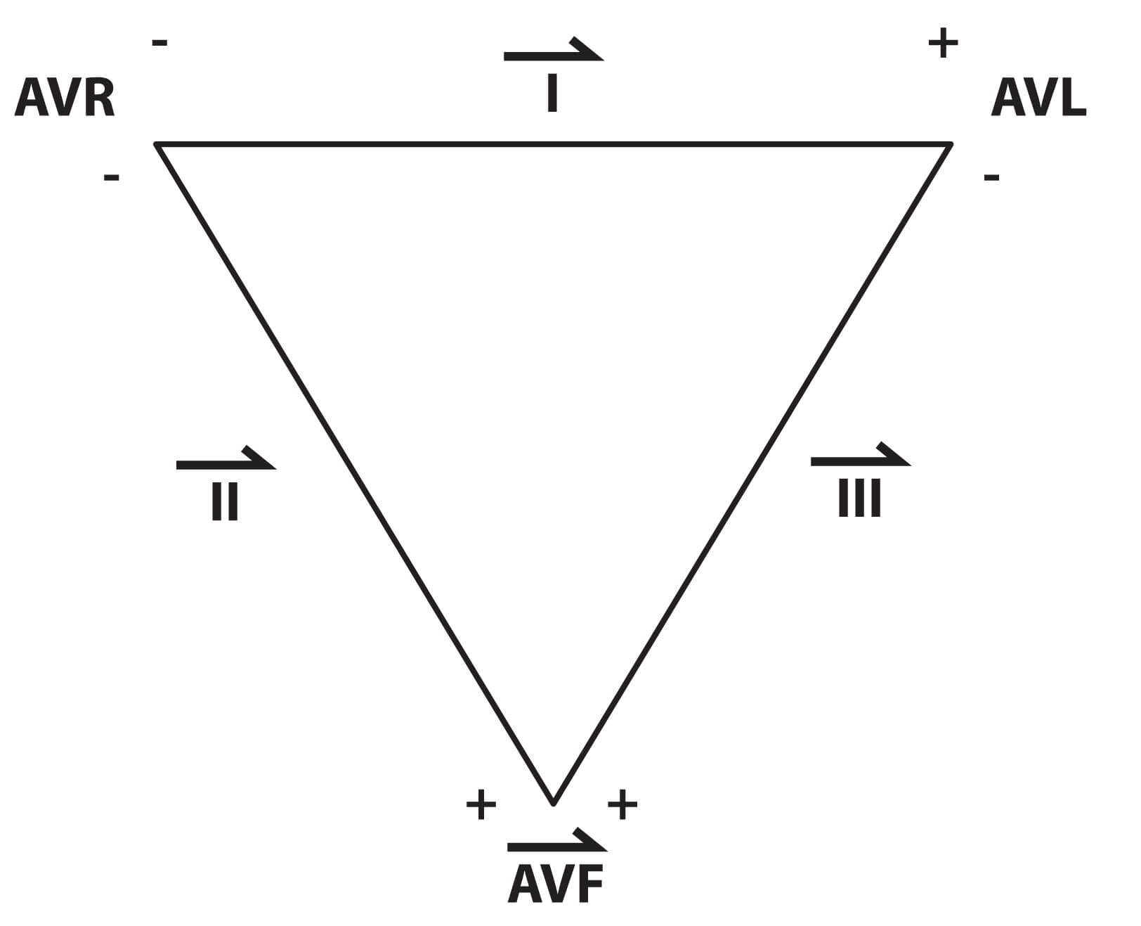
Figure 4. Einthoven’s triangle. © Medical Exam Prep
Information is gathered between these leads to create three more vectors:
- Lead I – information between AVR and AVL
- Lead II – information between AVR and AVF
- Lead III – information between AVL and AVF
The sum of these vectors is shown below in figure 4:
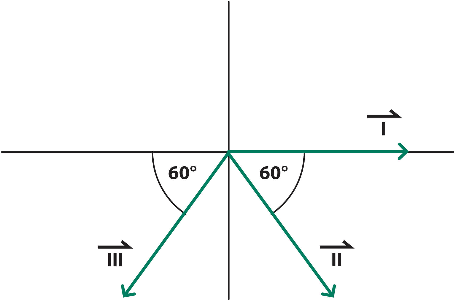
Figure 5. Limb leads I, II and III. © Medical Exam Prep
Finally by combining all 6 of these vectors together we create the ‘hexaxial system’, which gives us a perspective of the view of all six of the limb leads.
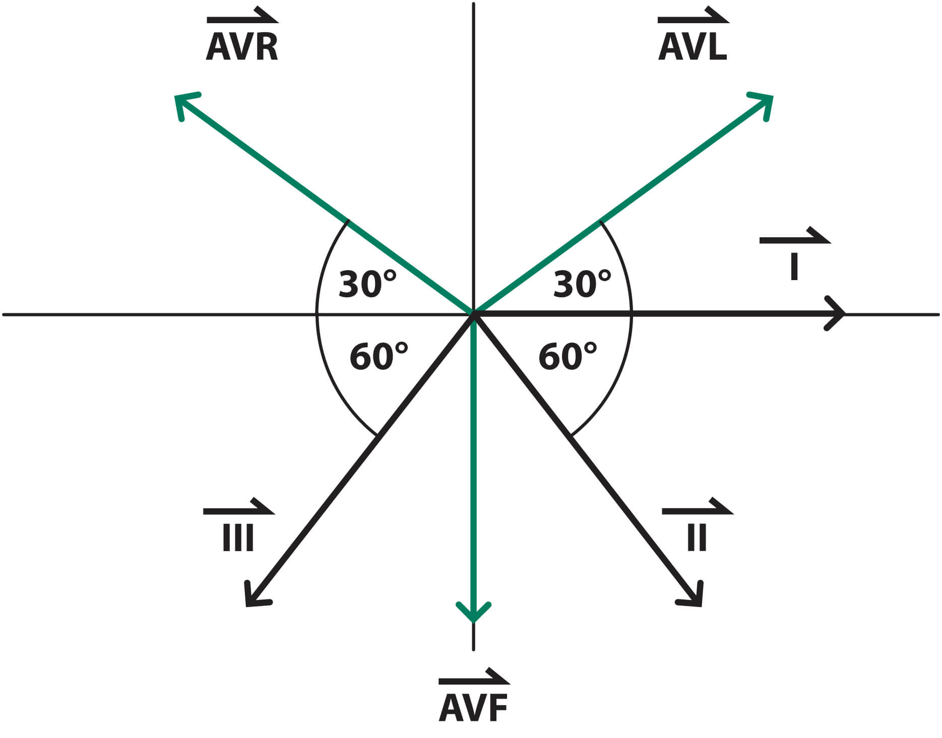
Figure 6. The ‘hexaxial system’. © Medical Exam Prep
We will return to the concept of the ‘hexaxial system’ later when we consider the calculation of the axis of the ECG.
Next: The Basics of ECG Interpretation (Part 2 – Rate, Rhythm and Axis)
Thank you to the joint editorial team of www.mrcemexamprep.net for this article.


Very nice topic… thank you very much for the informations.
It was nice…
thanks
Its difficult topic everytime have to study again and again,
U make it easy and digestible thanks
Nice presentation
Thanks a lot respected authority team for given such easy and detailed basic explanation.
Easy way to understand
Verry good topic
thanks
Nicely explained, easy to understand.
Really very educative and nicely explained.It will be easier for doctors and also for beginners to understand the fundamental basics of ECG.
Nicely presented
Nice and Awsome
Very nice topic… thank you very much for the information
Good topic is very good for you. I understand a lot
Nice topic awesome
Too good
Quite a good explanation, nurses will understand ECG better
Sehr interessant und gute Erklärung